Compressor Pad Restoration at a Glance
Industry
Power Generation
Location
Maharashtra, India
Service
On-Site Milling
Duration
19 days
Compressor and Motor Base Pads Out of Flatness
During a routine inspection, the maintenance team identified that the compressor and motor base pads had developed surface irregularities that fell outside the allowable flatness tolerance. Years of operational load and vibration had gradually worn the mounting surfaces out of the flat, level condition they needed to hold correct shaft alignment.
Left uncorrected, the misaligned base pads would have continued to put uneven stress on the compressor and motor bearings, increasing the risk of vibration, premature bearing failure, and an eventual unplanned shutdown.
Alignment Risk
Out-of-flat base pads mean the compressor and motor shafts can no longer be aligned within tolerance, no matter how carefully the coupling itself is adjusted.
Escalating Wear
Left in place, an uneven mounting surface introduces a constant, repeating stress cycle on the bearings every time the equipment runs, accelerating wear that would otherwise take years to develop.
Downtime Risk of the Conventional Fix
The standard repair path, disconnecting the equipment and sending the base pads out for resurfacing, would have meant an extended shutdown the plant couldn’t absorb.
Cost of Getting It Wrong
A base pad repair that doesn’t hold tolerance is worse than no repair at all, since it creates a false sense of the problem being solved while the underlying stress cycle continues.
Why It Was Caught Now
Routine inspection intervals are what caught this before it progressed to a bearing failure. Equipment running without periodic flatness checks often doesn’t surface this kind of issue until something actually breaks.
✓ On-Site Milling Execution
✓ Laser Measurement Verified
✓ Alignment Tolerance Achieved
✓ Downtime Minimised
Restoring Flatness On-Site, Without Dismantling the Equipment
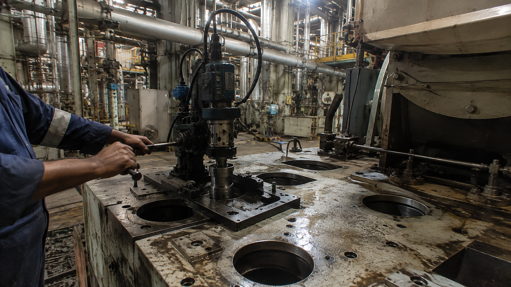
Our team began with a full dimensional inspection of the compressor and motor base pads, mapping the existing surface profile with laser measurement to identify exactly where the high and low points were before any machining began. That survey became the basis for the machining plan, rather than assuming the correction needed was uniform across the surface.
A portable milling unit was then mounted directly onto the base pads, and the surfaces were machined flat in controlled passes, with measurement checks between each pass to confirm progress against the target tolerance.
Dimensional Survey
Laser measurement was used to map the existing surface before machining, giving an accurate picture of deviation rather than relying on a visual estimate.
Equipment Stayed in Place
The compressor and motor remained in position throughout, avoiding the crane time, rigging, and reinstallation a conventional removal-and-resurface repair would have required.
Controlled Machining Passes
Material was removed gradually rather than in one aggressive pass, keeping the correction predictable and reducing the risk of over-cutting either surface.
In-Process Measurement
Flatness was checked between passes rather than only at the end, so the team could confirm progress was tracking toward the target tolerance throughout the job.
Step-by-Step: On-Site Milling for Compressor Pad Restoration
The same four-stage process we follow on every on-site milling job was used here, adapted to this equipment and site.
Site Assessment
Inspected both base pads and measured flatness deviation across the full surface before planning any correction.
Machining Plan
Set the target flatness and mounting method based on the measured survey, not an assumed uniform correction.
On-Site Milling
Machined both surfaces in controlled passes, with the compressor and motor left in position throughout.
Verification
Re-measured both pads to confirm flatness was within the required tolerance before handover.
Base Pads Restored to Engineering Tolerance
The on-site milling work restored the compressor and motor base pads to the flatness tolerance the original design called for. With both surfaces true again, the shaft alignment between the compressor and motor could be set correctly, removing the uneven load path that had been building on the bearings.
Because the work was carried out directly at the plant, the client avoided the disassembly, transport, and reinstallation a conventional repair would have required, and the compressor train was back in service without an extended shutdown.
What This Prevented
- Progressive bearing wear from uneven load
- Vibration-related component fatigue
- An unplanned shutdown for equipment removal
- The cost of resurfacing off-site
Equipment & Techniques Involved
Motor Mounting Surfaces
On-Site Milling
Laser Flatness Measurement
Shaft Alignment
Common Questions
Why not just re-shim the coupling instead of milling the base pads?
Shimming can compensate for some misalignment, but it doesn’t correct an out-of-flat mounting surface. Left uncorrected, the underlying surface issue continues to introduce stress every time the equipment runs, regardless of how the coupling is adjusted.
How do you know how much material to remove?
The dimensional survey taken before machining maps the actual deviation across the surface, so material is removed only where measurement shows it’s needed, not as a blanket skim across the whole pad.
Could this have been avoided with earlier maintenance?
Base pad wear develops gradually over years of operation, and periodic alignment checks can catch it before it reaches this stage. Routine laser alignment inspection is a lower-cost way to catch this kind of drift early.
Explore the Service Behind This Project
On-Site Milling
Restoring flat surfaces, mounting pads, and gasket faces on equipment that can’t practically be removed for workshop repair.
Have a Similar Problem on Your Equipment?
If base pads, mounting surfaces, or gasket faces on your equipment have drifted out of tolerance, our engineers can assess it on site and recommend the right fix.